
Reverse Engineering in NX: Turning Scan Data into Clean CAD
A practical guide to reverse engineering in Siemens NX — converting STL and scan data into usable CAD surfaces and solids for redesign, tooling and manufacturing.
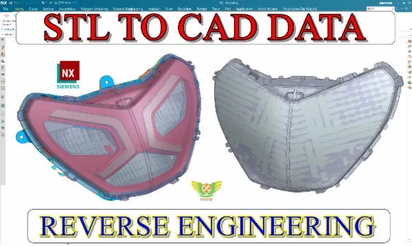
Not every part comes with a CAD file. Legacy components, competitor samples, worn spares and hand-made prototypes often exist only as physical objects. Reverse engineering is the skill of turning those objects — via 3D scanning — into clean, editable CAD. In Siemens NX, it’s a powerful and highly employable capability.
What reverse engineering really involves
The input is usually a 3D scan: a dense point cloud or STL mesh that captures the part’s surface but isn’t editable CAD. Your job is to interpret that data and rebuild the part as proper surfaces and solids — accurate to the scan, but clean enough to modify and manufacture. It’s part detective work, part surfacing craft.
The reverse-engineering workflow
A reliable process turns messy scan data into a usable model:
- Import and align the STL/scan data to a sensible coordinate system.
- Analyse the geometry — identify planes, cylinders, fillets and freeform regions.
- Extract curves — section curves and feature lines that describe the shape.
- Build surfaces over the curves, checking deviation against the scan.
- Stitch and thicken into a watertight solid.
- Validate the model against the original data for accuracy.
Practising this loop on real scans — from consumer parts to automotive components — is what builds speed and judgement.
Surfacing is the core skill
The heart of reverse engineering is surfacing: creating smooth, controlled surfaces that match the scanned geometry without inheriting its noise. Learning to balance accuracy (staying true to the scan) against quality (clean, editable surfaces) is the craft that separates a usable model from an unusable one.
Where reverse engineering pays off
The applications are everywhere:
- Spare-part manufacturing for components with no drawings.
- Redesign and improvement of existing products.
- Tooling and moulds built from a physical master.
- Inspection — comparing manufactured parts to intent.
Because the need is so broad, engineers who can confidently convert scan data to CAD are in constant demand.
Getting started
Begin with simpler parts to learn alignment, curve extraction and basic surfacing, then progress to complex freeform components. Pair reverse engineering with strong NX modelling, and you’ll be able to take almost any physical object and give it a clean digital life — ready for redesign, tooling or manufacture.
Frequently asked questions
- What is reverse engineering in CAD?
- It's the process of taking a physical part's 3D scan (often an STL point cloud or mesh) and rebuilding it as clean, editable CAD surfaces and solids you can modify, tool up or manufacture.
- Why is reverse engineering a valuable skill?
- Many parts exist only as physical samples or legacy components with no CAD. Reverse engineering recreates their digital models for redesign, spare-part manufacturing, moulds and quality inspection.
- Do I need strong surfacing skills?
- Yes — surfacing is central. The course builds the workflow from scan data through curves and surfaces to a finished solid, so you develop exactly the surfacing skills the job needs.